Standard drive sprocket materials are:
Idler shafts can be fitted with flanged and support rollers. Support rollers should be placed on all shafts every 250 to 300 mm to minimize bending of the cross rods.
Drive sprockets and idler rollers should be placed in such a way that the belt is lifted from the belt support rail by 1 or 2 mm. If the wheels are placed lower than the support rails the belt is pulled into the support rail which can result in excessive wear on belt and support rails, increased belt tension, tracking problems etcetera.
TBU 30 Drive Sprockets – Pitch 30 mm
| Number of teeth | Pitch circle diameter (in mm) | Hub diameter (in mm) | Outside diameter (in mm) | Support roll diameter (in mm) | Flange roll diameter (in mm) |
|---|---|---|---|---|---|
| 12 | 117,1 | 100,1 | 125,1 | 103,9 | 100,1 |
| 16 | 155,4 | 139,4 | 164,4 | 143,2 | 139,4 |
| 22 | 203,4 | 188,1 | 213,1 | 191,9 | 188,1 |
TBU 40 Drive Sprockets – Pitch 40 mm
| Number of teeth | Pitch circle diameter (in mm) | Hub diameter (in mm) | Outside diameter (in mm) | Support roll diameter (in mm) | Flange roll diameter (in mm) |
|---|---|---|---|---|---|
| 12 | 155,6 | 135,3 | 164,3 | 140,1 | 135,3 |
| 16 | 206,4 | 187,4 | 216,4 | 192,3 | 187,4 |
| 22 | 270,1 | 252,1 | 281,1 | 256,9 | 252,1 |
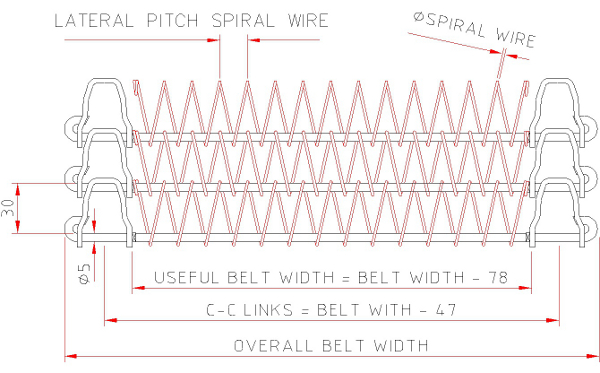
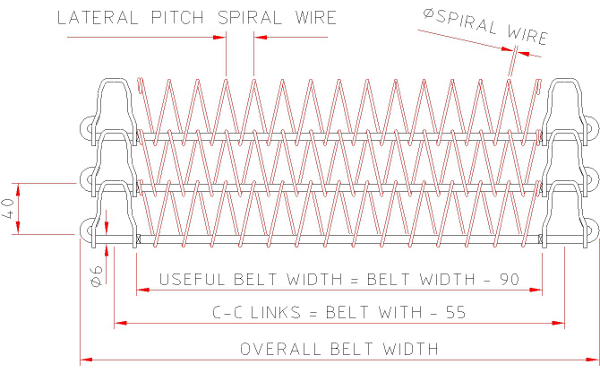
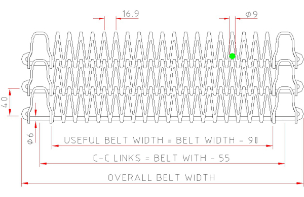
TwenteFlex belts are developed to obtain optimum contact between belt edge and inner guide rail. The innovative bended rod design eliminates breakage of rod and button head due to welding. The elimination of welding ensures full material quality and belt strength.
Design guidelines
TwenteFlex TBU 30
TwenteFlex TBU 40
Belt support
General recommendations
Installation and commissioning of belts
Installing a belt properly is essential in ensuring a good performance of a conveyor system. Making sure that your belt will be used to its full extent, Twentebelt can install the belt, and / or assist your team in installing it. Twentebelt also offers the commissioning of belts as a service.
Click here to request more information about our services
System design
Take-up
Cage overdrive
In most applications it is recommended to have a cage overdrive setting of approximately 800 to 1200 mm per tier revolution faster than the belt (measured between the cage and the inside belt edge). Increasing the cage overdrive will decrease the belt tension and increase the possibility of the belt surging.
The optimal overdrive setting is reached just before the belt starts surging, making sure the belt can be pulled from the cage by hand force at least 1 to 2 centimeters.
Operation
Clean the belt and supports regularly to avoid high belt tensions due to an increased friction caused by product contamination. Prevent excessive ice build-up in freezers.
Belt support rails
There must be at least 50 mm free space between the drum and the inner support rails at all times to prevent the links being crushed between them. The advised distance between the support rail and the belt edges is 60 to 90 mm. In general, the advised number of support rails is as follows:
| Belt width (in mm) | Number of supports |
|---|---|
| ≤ 610 | 2 |
| 611 - 1016 | 3 |
| 1017 ≥ | 4 |
The common used belt support material is PE-1000 or PE-500 High Density Poly Ethylene. Other materials are possible depending on the application. The advised width of the support rail is 15 mm. Smaller widths of the rail could increase movement of the spiral overlay. Widths smaller than 10 mm are therefore not recommended. The side of the support rail must be rounded.
Cage / Drum bars
In order to obtain a smooth drive it is recommended to use cage bars that are 45 to 60 mm wide with a flat drive surface and a 3×3 chamfer spaced apart approximately 120 mm. At temperatures below 60° Celsius the recommended material is PE-1000. For applications with temperatures over 60° Celsius stainless steel cage bars or a full stainless steel cage can be used. If stainless steel is used for cage drive surface, the overdrive can be decreased to 400 to 600 mm due to the increased friction coefficient. Keep in mind the belt edge will wear more quickly on a stainless steel cage surface.
It is recommended that the cage bars are covering at least 20% of the cage.
Wider cage bars spread out the total generated friction drive force over more cross rods which decreases the force per cross rod directed to the cage middle and thus decreases the bending of the cross rod. Reducing the bending of the cross rods will optimize the drive generated by the friction between belt and cage bars. The energy needed to bend the rodscan not be converted into drive force. Because the cage moves faster than the belt, the cross rods are exposed to cyclic loading each time the cross rod passes a cage bar. Reducing cross rod bending will extend belt life and create a smoother belt run.
It is recommended to maximize the width and number of cage bar strips on the cage as much as possible, especially when running spiral systems with high loads.
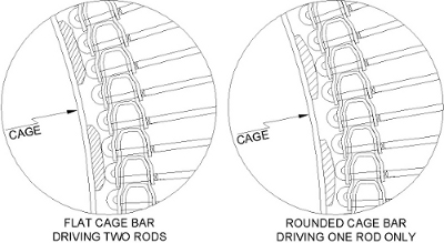
The use of rounded cage bars can result in undesired movement of the inside links. Depending on the radius of the cage bars it is possible that only one cross rod is in contact with a cage bar. This can cause sudden undesired movement of this rod when it passes the top of the cage bar radius. A flat drive surface almost equals the cage radius. It is recommended to select a cage bar that is wide enough to drive at least two collapsed cross rods. Below is a picture with two cage bar designs. The cage bar design on the left is recommended, while the design on the right is not preferred.
Fitting the belt
When replacing the old belt with a different pitched belt, the pitch circle diameter of the drive sprockets may be different. Be aware that this changes the belt speed and thus the overdrive of the cage. If the new sprocket is smaller in diameter make sure that the belt is not pulled into the belt support rails. When replacing an old belt it is recommended to re-new the cage bars, belt support rails and sprockets / rollers.
Instructions:
Due to the design of this belt there is a possibility that links can lock themselves in a tented position while pulling in the belt. Please check the complete belt after fitting it and remove any such tents before operating the belt. This tenting of links can not occur in operating conditions because links are always extended when bent around rollers.
Splicing or shortening
When the belt has to be spliced together it is recommended to use a supplied connector rod. This rod is bent at one end and can be secured with a nut at the opposite end.
Shortening the belt
| Belt type | Material | Pitch | Lateral pitch | Cross rod diameter | Wire mesh diameter | Inside turn radius | Sprockets | |
|---|---|---|---|---|---|---|---|---|
| TwenteFlex Full Metal | TBU 30 | Stainless Steel | 30 mm | Ranging from 4.2 to 16.9 mm | 5 | 1.2. mm, 1,4 mm or 1.6 mm | Ranging from 1.7 to 2.2 times the belt width | With 12, 16 or 21 teeth |
| TBU 40 | Stainless Steel | 40 mm | Ranging from 4.2 to 16.9 mm | 6 | 1.2. mm, 1,4 mm, 1.6 mm or 1.8 mm | Ranging from 1.6 to 2.2 times the belt width | With 12, 16 or 21 teeth | |
| TwenteFlex Hybrid | TBU 40P | Stainless Steel and Acetal (POM) | 40 mm | Ranging from 16,9 mm to 53% of the open area | 6 | Not applicable | Ranging from 1.6 to 2.2 times the belt width | With 12, 16 or 21 teeth |
![]() Twentebelt TwenteFlex conveyor belts – Data sheet TBU-30 – English
Twentebelt TwenteFlex conveyor belts – Data sheet TBU-30 – English
![]() Twentebelt TwenteFlex conveyor belts – Data sheet TBU-40 – English
Twentebelt TwenteFlex conveyor belts – Data sheet TBU-40 – English
![]() Twentebelt TwenteFlex conveyor belts – Data sheet TBU-40P – English
Twentebelt TwenteFlex conveyor belts – Data sheet TBU-40P – English
![]() Twentebelt TwenteFlex conveyor belts – Curved conveyor guidelines – English
Twentebelt TwenteFlex conveyor belts – Curved conveyor guidelines – English
![]() Twentebelt TwenteFlex conveyor belts – Fitting instructions – English and German
Twentebelt TwenteFlex conveyor belts – Fitting instructions – English and German
![]() Twentebelt TwenteFlex conveyor belts – Technical information and guidelines – English
Twentebelt TwenteFlex conveyor belts – Technical information and guidelines – English
Require additional assistance?
Do you require additional technical information? Or do you have a specific question for our engineering team? Click on the button below to fill out a form and we will be in touch shortly.
Contact Twentebelt
Request a quotation
Requesting a quotation for a TwenteFlex conveyor belt is easy. Simply click on the button below, fill in your specifications and our experienced sales team will get back to you as soon as possible.
Request a TwenteFlex quotation