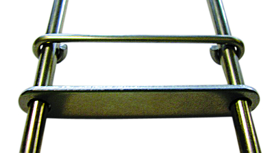
The image below shows an eyelink, plate link and cross rods.
The following materials are used for Twentebelt eyelink conveyor belts:
Other materials are available on demand and/or on advice.
Twentebelt offers a variety of eyelink belts.
Full eyelinks (DO)
The basic principle of all eyelink conveyor belts versions. On a full eyelink belt the eyelinks lie against each other, and the opening is equal to the wire diameter. This method can best be used for products likely to fall, or for applications that require small openings.
Pressed eyelinks (DP)
Some applications require the smallest opening possible. By flattening the eyes of the eyelinks the opening between the links becomes smaller. This method is very appropriate for small and fine-structured products.
Welded eyelinks (DL)
The eyelinks are welded on to an location wire, so that a module is created. Very narrow and very wide openings can be created, depending on the processing of the products concerned. The eyelinks can be set according European or American assembly, depending on the requirements of hygiene. The standard method is the use of one location wire. The use of more than one location wire will not make the belt more solid. Its only function is related to the dimensions of the product (the desired drain). Modular eyelink conveyor belts are stable, also in dimensional respect. The minimal opening is equal to the eyelink diameter + 0,05mm.

Pressed and welded eyelinks (DPL)
Some applications require a stable belt in combination with a small opening/drain. The accuracy of our welding process allows us to produce modules with very small intervals between the eyelinks. The modular structure makes the assembly of very broad belts possible.
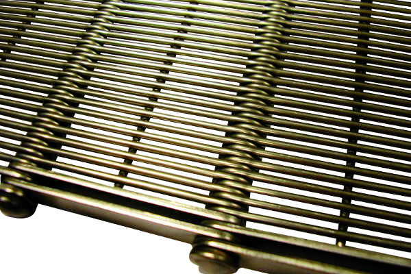
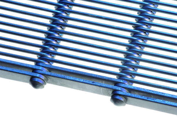
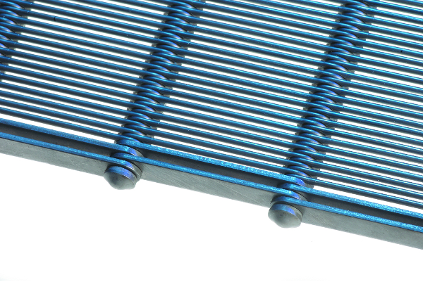
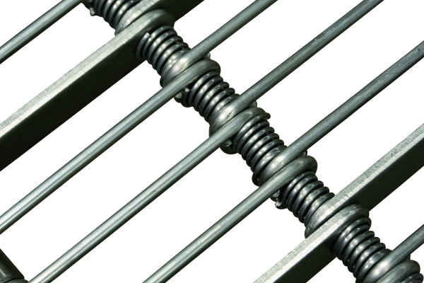
Eyelinks with springs (DV)
The placement of springs between the eyelinks ensures that they are positioned at regular intervals. The result is a relatively light belt with specific qualities, such as a good shock resistance and resistance to lateral forces. This is important in situations when the conveyor belt is loaded manually and/or laterally.
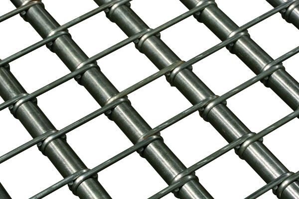
Eyelinks with bushings or washers (DB)
Bushings or washers are meant to create an opening between the eyelinks. When bushings or washers are added the belts become heavier and more rigid.
Twentebelt offers 4 different side finishes for its eyelink conveyor belts.
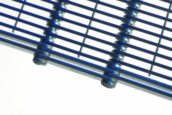
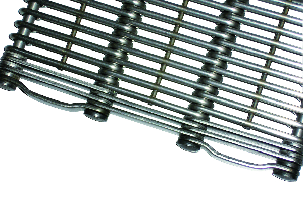
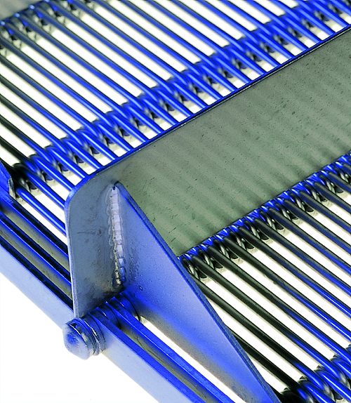
Welded edge (LK)
At both sides the belt is fitted with plate links, and the far ends of the cross rods are fitted with washers and subsequently welded. This results in a thorough finishing of the belt in combination with the desired bearing surface.
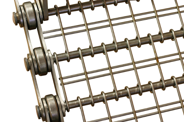
Side chains (KH)
Eyelink conveyor belts are usually fitted with chains, if the belt is to perform a negative bend. For this purpose only hollow pin roller chains are used with pitch measurement equal to those of the belt. The selection of the chains depends on the operating conditions.
Guide plates (GP)
Guide plates serve as a protection for the welding heads. The plates actually function as a “buffer” between the welding heads and the guidance or other constructions the sides of the belt can get in touch with.
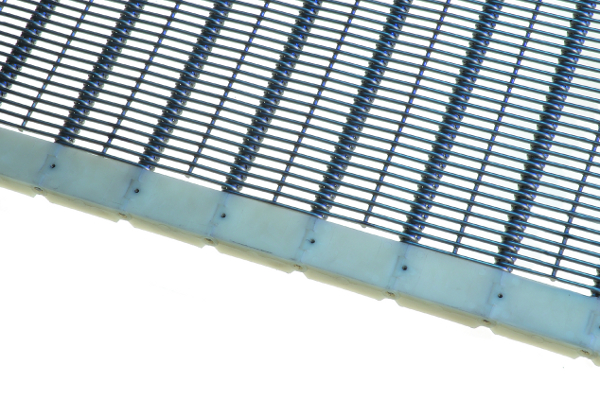
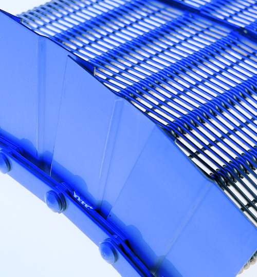
Plastic blocks (KB)
Plastic blocks are a patented item of Twentebelt. This product has several functions, which among other things improve the modular qualities of the eyelink belt (no welds), and generally also the hygiene.
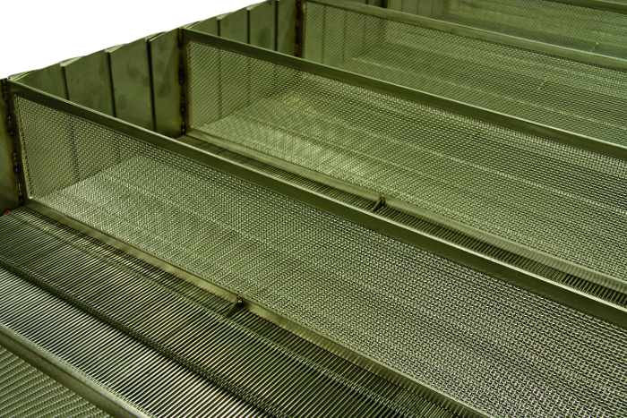
Edge plates
All Twentebelt eyelink conveyor belts can be provided with edge plates that make it possible to control the layer thickness of the product to be transported. The height and the shape of the edge plates can be adapted to the sort of product and to the process.
Flights
For ascending and/or descending eyelink belts, flights can be fitted. The shape, measurements and structure (open / closed) of the flights will again be adapted to the sort of product and to the process.
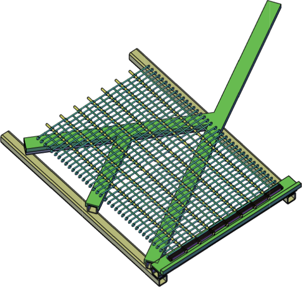
Example of eyelink conveyor belt featuring both edge plates and flights
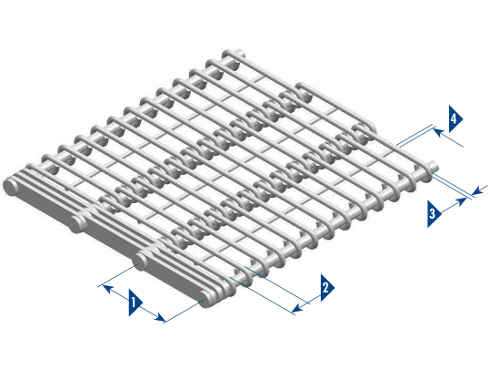
1 – Pitch: Centre-to-centre distance of cross rods (ranging from 15,9 to 76,2 mm)
2 – Cross pitch: Centre-to-centre distance of eyelinks (ranging from 2,8 to 50 mm)
3 – Wire diameter (ranging from 1,6 to 3,2 mm)
4 – Number of location wires (ranging from 0 to 8)
Explanation of specification method for eyelink belts.
DL-LK 6 – 50 – 2,5 – 5 location wires 1
DL-LK: Welded eyelinks with welded edges
6: Cross-pitch (mm)
50: Pitch (mm)
2,5: Wire diameter (mm)
5: Cross bar wire diameter (mm)
| Pitch (mm) | Wire diameter | Cross rod diameter | Minimal centre-to-centre distance between 2 eyelinks | Minimal centre-to-centre distance between 2 eyelinks in welded version |
|---|---|---|---|---|
| 15,9 | 1,8 | 3,2 | 3,6 | Not applicable |
| 25,4 | 1,6 | 5 | 3,2 | 3,25 |
| 2 | 4 | 3* | ||
| 30 | 1,6 | 4 | 3,2 | 3,25 |
| 2 | 4 | 4,05 | ||
| 38,1 | 2 | 8 | 4 | 4,05 |
| 2,5 | 5 | 5,05 | ||
| 3 | 6 | 6,05 | ||
| 50 | 1,6 | 5 | 3,2 | 3,25 |
| 2 | 5 | 4 | 3* | |
| 2,5 | 5-7 | 5 | 5,05 | |
| 3,2 | 6 | 6,4 | 6,45 | |
| 50,8 | 2 | 5-8 | 4 | 3* |
| 2,5 | 5-8 | 5 | 5,05 | |
| 3 | 8 | 6 | 6,05 | |
| 75 | 2,5 | 5-8 | 5 | 5,05 |
| 3 | 8-10 | 6 | 6,05 | |
| 76,2 | 3 | 10-13 | Not applicable | 6,05 |
* Pressed and welded, type DPL
Generally two configurations are possible to provide eyelink belts with support: longitudinal support or herringbone support.
Longitudinal support for eyelink belts
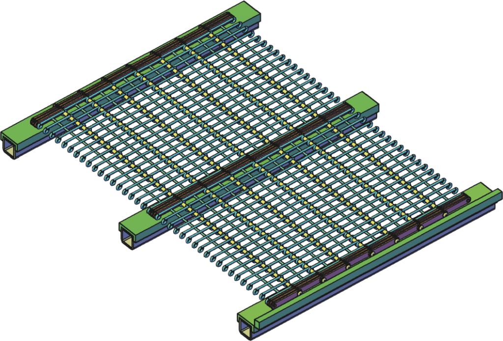
The longitudinal support consists of support sections fitted in the longitudinal direction of the installation. These sections are placed at both sides and depending on the width and the load, about every 300 mm right across the width of the belt (see drawing). At the height of those support sections, rows of plate links must be fixed, which will convey the load to the underlying support sections. Depending on the load these rows will consists of one or more plates.
Herringbone support for eyelink belts
In a herringbone support structure the support sections (as the name suggests and the drawing illustrates) are positioned in the form of a fish bone. In this case it will be sufficient to place rows of plate links at the edges only. The bearing function will be taken over by the eyelinks. As all eyelink hit the support strips some time or other, the wearing pattern will be equally spread across the full width of the belt. With this support the product will be equally processed across the full width of the belt. Possible shadow zones, as is the case in longitudinal support structures, will not occur here.
If hygine is even a more important issue than usual, we advise you to provide the belt with plate links at the edges only. Because of their round shape eyelinks are easier to clean than plate links. In such a construction the frame will be constructed with a herringbone support, so that filth falling through the belt will immediately be pushed away from the support strips.
Support return path
The return path only carries the weight of the belt. This is why a lighter support structure is sufficient here. In the longitudinal construction one of two profiles can be left out. The herringbone support can be executed in a less compact form. In the return path, the first 500 mm of the belt slacken. There is no support in order to make the formation of a sag possible. The formation of a sag will prevent the belt from climbing on to the drive. It is also necessary in order to prevent the belt from being pushed instead of pulled through the return path. At both ends the support sections should be slightly bent down, in order to establish a gradually guidance of the belt on to and off the profiles.
Rollers can also serve as a support to restrict the frictional coeffecient. The rollers must be at right angles to the frame, parallel to each other and level. The distance between the rollers is irregular, in order to prevent an irregular run.
Frictional coefficient
Below you will find an indication of the frictional coefficient for the different alternatives:
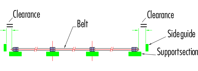
Side guidance is achieved by vertical profiles at both sides of the installation. These profiles should not get in contact with the belt. They are meant to guide the belt in case it deviates from the carrying path. A clearance of 5 to 10 mm between the profiles and the belt is basically sufficient. The geometry of the frame and the load of the belt are points of attention in the design and the adjustment of the installation, because these factors can influence the run of the belt.
The minimal facility at the input side consists of profiles both on top and on the underside, at the discharge side, however, only on top. The maximal facility consists of profiles over the full length of the carrying path and the return path with the exception of the sagging part. The compromise is the placement of profiles of 300 to 500 mm length every 2000 mm. The appropriate configuration is also determined by the speed, the length, the width and the load of the belt.
In case of doubt, please do not hesitate to contact us. We will be pleased to think along with you.
Sprockets
Generally, eyelink conveyor belts are driven directly on the eyelinks by means of specially developed drive sprockets. For DO belts these sprockets are provided with block teeth. In the case of DL belts the sprockets are constructed such that they exactly match the profiles at the underside of the belt. In case of belts with a large cross pitch (centre-to-centre distance of eyelinks) one could consider to place sprockets that are directly driven on the cross rod instead of on the eyelinks. Generally the sprockets are placed at both sides and under each row of plate links. The width, the number of teeth and the material of the sprockets are determined on the basis of the conditions of use.
When a construction of drive sprockets is applied in a freezer, sprockets with special toothing are used. In order to prevent the accumulation of ice, the so-called ‘ice-crusher’ sprockets are used. The special toothing limits the accumulation of ice to the minimum.
Sprockets are available in steel, AISI 304 (WS 1.4301), AISI 316 (WS 1.4401), PA6G and POM, or in other materials on request or on advice. An example of a stainless steel sprocket is featured below.

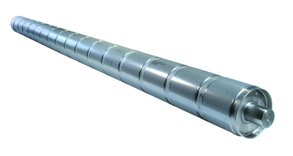
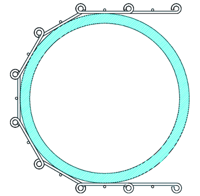
Cage rollers
Broad and heavily loaded eyelink conveyor belts are preferably driven by rollers right across the width of the belt, cage rollers in most of the cases. The straps of the roller regularly drive all the eyelinks of the pitch, which is conducive to a longer life span of the belt and also leads to a regular wear pattern.
Disc rollers
If there is a risk of accumulation of filth or ice, disc rollers should preferably be used. On a multiple of the cross pitch these rollers are provided with discs. These discs can be produced in different ways, so that different properties can be created:

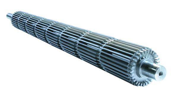
Tube rollers
In the grooves of tube rollers with replaceable strips, plastic or soft-metal strips are placed. In case of tube rollers with replaceable teeth, the teeth are welded. This construction has three advantages:
In general, tube rollers drive long, broad and heavily loaded belts.
Chain sprockets
Eyelink belts can also be produced with chains, whereby the chain fulfils a driving function. Especially when the belt has to perform a negative bend, as is the case with many applications for freezing or blanching, and for ascending belts. In those applications the side-sprockets are replaced by chain sprockets belonging to the chain applied.
In this case, too, the rule applies that for bigger constructions chain sprockets will be placed in combination with a roller.
In all applications with chains a negative bend of the belt can easily be achieved by means of chain sprockets or wear strips of the hollow pin roller chain. Twentebelt prefers the use of sprockets with at least 12 teeth. This is based on the fact that with this number of teeth the so-called polygon effect will exert hardly any influence on the belt run. If the length and the load of the belt are moderate drive sprockets with a minimum of 8 teeth might be used. The ultimate determination of the necessary number of teeth depends on factors like width, length, load and running speed of the belt.

[Pitch diam. calculation]
The pitch diameter of sprockets and rollers can be determined by multiplying the number in column n, which is related to the desired number of teeth (column Z), by the pitch of the belt (T).
| Z - n | Z - n | Z - n |
|---|---|---|
| 8 - 2,6131 | 16 - 5,1258 | 24 - 7,6613 |
| 9 - 2,9238 | 17 - 5,4422 | 25 - 7,9787 |
| 10 - 3,2361 | 18 - 5,7588 | 26 - 8,2962 |
| 11 - 3,5495 | 19 - 6,0755 | 27 - 8,6138 |
| 12 - 3,8637 | 20 - 6,3925 | 28 - 8,9314 |
| 13 - 4,1786 | 21 - 6,7095 | 29 - 9,2491 |
| 14 - 4,494 | 22 - 7,0267 | 30 - 9,5668 |
| 15 - 4,8097 | 23 - 7,3439 | 31 - 9,8845 |
Pitch circle diameter value for n (dst = n x T)
As for the return shaft there is a choice between toothed or smooth wheels or rollers. In principle, toothing only has a function in case of accumulation of ice or filth. Toothing on the return shaft consequently has no drive function. Generally, in small installations one prefers to provide the return shaft with toothed wheels. When, however, a cage roller was chosen to drive the belt, a smooth roller will be chosen for the return shaft. An exception to this is a drive with cage rollers and chain wheels, whereby the same construction is used as a return roller.
If provided with one tooth per pitch the rollers are one-directional and thus only to be used for drive or for return. Rollers with double strips can be used for both drive and return, if the installation is designed for this purpose.
Of course, this depends on the length and the load. In general, the return shaft is the one for tensioning and adjustment. In case of short belts and insufficient geometry of the frame this can lead to a bad drive (see drawing below).
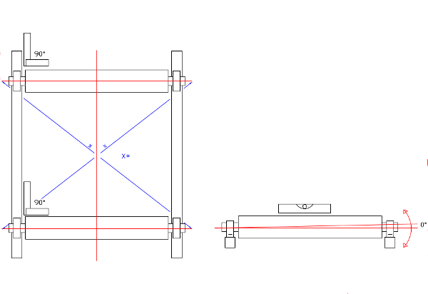
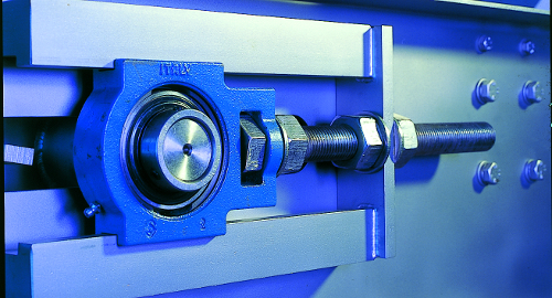
In most cases a screw tensioning device will suffice. An example of a screw tensioning device can be seen below.
In the case of a continuous tensioning device, hydraulic, pneumatic or with springs, there is always the risk of a certain amount of uncontrolled stretching that tends to elongate the belt. The table below provides the tensioning length per pitch. It has to be taken into account when the shaft has to be adjusted. The tensioning force = (the weight of the belt in the return part x the friction coefficient) x 9,8.
| Pitch | Tensioning length |
|---|---|
| 15,9 | 45 |
| 25,4 | 75 |
| 30 | 90 |
| 38,1 | 110 |
| 50/50,8 | 150 |
| 75/76,2 | 250 |
Temperature
Eyelink conveyor belts can be used within a relatively broad temperature range. See the table for more information.
| Material | Minimum temperature in °C | Maximum temperature in °C |
|---|---|---|
| Steel | 0 | 220 |
| AISI 304 | - 80 | 350 |
| AISI 316 | - 80 | 350 |
Speed
The maximum constant speed is 25 m/min. Brief peaks in speed up to 60 m/min. are possible with reservation. Eyelink conveyor belts provided with chains limit the maximum speed to 25 m/min.
Load
Because of the many variable factors of eyelink belts the permitted load will be determined on request.
Negative bend
In case of negative bends of DL-type eyelink belts, a point concentrated load can occur in the zone of the location wire. As a result of repeated minimal bends the eyelinks can break. The use of special guidance strips with a wide radius offers a solution.
Cleaning
The materials we use for the production of our belts are suitable for contact with food.
Because of the risk of filth during the assembly in, the belt should preferably be cleaned after the installation!
Please note:
Drive and return wheels are often produced in plastic versions. In that case they are not resistant to certain cleansers. You are kindly requested to keep to the valid cleansing procedures during the installation of your machine, and, if necessary, to adjust the choice of your materials to them.
Below you will find downloads related to eyelink conveyor belts.
![]() Twentebelt Eyelink conveyor belts – Technical brochure – English
Twentebelt Eyelink conveyor belts – Technical brochure – English
![]() Twentebelt Eyelink conveyor belts – Request quotation form – Dutch
Twentebelt Eyelink conveyor belts – Request quotation form – Dutch
![]() Twentebelt Eyelink conveyor belts – Request quotation form – English
Twentebelt Eyelink conveyor belts – Request quotation form – English
Require additional assistance?
Do you require additional technical information? Or do you have a specific question for our engineering team? Click on the button below to fill out a form and we will be in touch shortly.
Contact TwentebeltRequest a quotation
Requesting a quotation for an eyelink conveyor belt is easy. Simply click on the button below to input your specifications and our experienced sales team will get back to you as soon as possible.
Request an eyelink conveyor belt quotation